New Holland T6030 Tractor Hydraulic Pump Pressure Test Guide
2022 New Holland Electronic Service Tools CNH EST Software Free Download
Procedures:
NOTICE:
Before performing any pressure or flow testing operate the tractor until the oil in the rear axle is at normal operating temperature. 65 °C ( 145 °F).
NOTICE:
A faulty compensating valve may cause the pump to be on load and operating at maximum pressure under all conditions. It is advisable to use a high pressure gauge 0 – 255 bar ( 0 – 3600 lbf/in2) to confirm the valve is operating correctly before using a low pressure gauge. Failure to follow this instruction may result in damage to the gauge.
NOTICE:
Before proceeding make sure the mid mount valves control lever or joystick (if equipped) is in the neutral position.
Low Pressure Standby
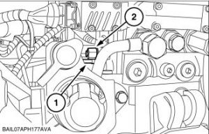
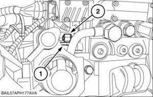
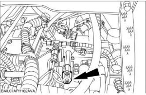
1.The following tests check operation of the hydraulic pump and associated high pressure circuits. Disconnect load sense line (1) to remote valves and install cap (2) 297604.
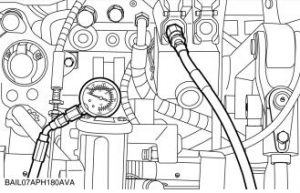
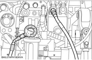
2.Attach 0 – 40 bar ( 0 – 600 lbf/in2) gauge 293242 to remote valve coupling using remote valve coupling 5101741 or 293449, adaptor 297606, quick release fitting 297240, quick release coupler 291924 and hose 292246.
Set engine speed to 1500 rev/min
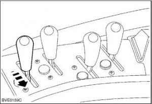
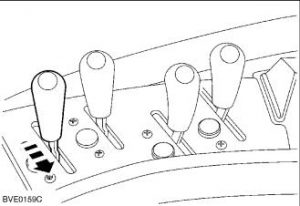
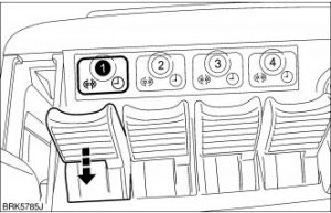
3.Pull and hold the respective remote valve control lever in the ‘extend’ position.
The pressure reading should be 26±1 bar ( 377±15 lbf.in2) is the ‘Low Pressure Standby‘.
NOTICE:
While the remote lever is in the operating position do not operate the tractor brakes, the mid mount valves or the axle suspension, otherwise the system pressure will increase to maximum pressure of 120 – 140 bar ( 1740 – 2031 lbf.in2), resulting in damage to the pressure gauge.
NOTICE:
On vehicles with Terraglide™ front axle the system may operate at startup resulting in maximum pressure being applied initially. Use a suitable high pressure gauge to make sure the system is inactive
In models with SideWinder™:
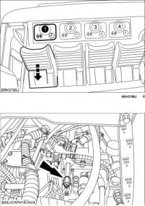
Pull and hold the respective remote valve control lever in the ‘extend’ position.
The pressure reading should be 26±1 bar ( 377±15 lbf.in2) is the ‘Low Pressure Standby‘.
NOTICE:
While the remote lever is in the operating position do not operate the tractor brakes, the mid mount valves or the axle suspension, otherwise the system pressure will increase to maximum pressure of 120 – 140 bar ( 1740 -2031 lbf.in2), resulting in damage to the pressure gauge.
NOTICE:
On vehicles with Terraglide™ front axle the system may operate at startup resulting in maximum pressure being applied initially. Use a suitable high pressure gauge to make sure the system is inactive.
4.If pressure reading is marginally away from specification adjust the flow compensating valve.
If reading is high examine the flow compensating valve spool for sticking.
NOTE:One full rotation will adjust the pressure by approximately 16 bar ( 232 lbf.in2).
5.Remove the cap (2) 297604. Reconnect the load sense line (1)
High Pressure Standby
6.Attach a 0 – 255 bar ( 0 – 3600 lbf/in2) gauge 293244 to remote valve coupling using remote valve coupling 5101741 or 293449, adaptor 297606, quick release fitting 297240, quick release coupling 291924 and hose 292246.
Set engine speed to 1500 rev/min
7.Pull and hold the respective remote valve control lever in the ‘extend’ position.
The pressure reading should rise to 210±5 bar (3046±73 lbf.in2) and is the ‘High Pressure Standby‘
In models with SideWinder™:Pull and hold the respectiveremote valve control lever in the ‘extend’ position.
The pressure reading should rise to 210±5 bar ( 3046±73 lbf.in2) and is the ‘High Pressure Standby‘
8.If reading is not to specification adjust the pressure compensating valve.
NOTE:One full rotation will adjust the pressure by approximately 50 bar ( 725 lbf.in2)
More information you can check here: https://www.cnautotool.com

